 English
 简体中文
简体中文  Español
  Português
  русский
  Français
  日本語
日本語  Deutsch
  tiếng Việt
  Italiano
  Nederlands
  ภาษาไทย
  Polski
  한국어
한국어  Svenska
  magyar
  Malay
Malay  বাংলা ভাষার
  Dansk
Dansk  Suomi
Suomi  हिन्दी
  Pilipino
  Türkçe
  Gaeilge
  العربية
  Indonesia
  Norsk
Norsk  تمل
تمل  český
český  ελληνικά
  український
  Javanese
  فارسی
فارسی  தமிழ்
தமிழ்  తెలుగు
  नेपाली
  Burmese
  български
  ລາວ
ລາວ  Latine
  Қазақша
  Euskal
  Azərbaycan
  Slovenský jazyk
  Македонски
  Lietuvos
  Eesti Keel
  Română
  Slovenski
  मराठी
मराठी


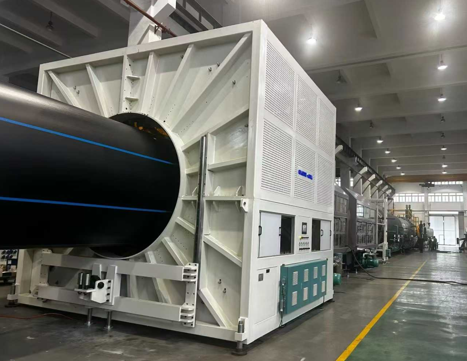
Key Points for Startup Equipment and Production Technology of PE Pipes with Large Diameters Above 2000mm
Ningbo Fangli Technology Co., Ltd. is a mechanical equipment manufacturer with nearly 30 years’ experiences of plastic pipe extrusion equipment, new environmental protection and new materials equipment. Since its establishment Fangli has been developed based on user’s demands. Through continuous improvement, independent R&D on the core technology and digestion & absorption of advanced technology and other means, we have developed PVC pipe extrusion line, PP-R pipe extrusion line, PE water supply / gas pipe extrusion line, which was recommended by the Chinese Ministry of Construction to replace imported products. We have gained the title of “First-class Brand in Zhejiang Province”.
Increasing urbanization and the growing impacts of climate change mean that freshwater supply and wastewater treatment are becoming increasingly critical. It is anticipated that this demand will persist and intensify. Over the years, the performance of plastic pipes in water management has improved through material optimization, advancements in equipment technology, and manufacturing methods. Due to the need for large water conveyance volumes, the requirement for larger pipe diameters is continuously increasing.
PE pipes have numerous successful applications and promotion cases in various fields such as water supply and drainage, gas, agriculture, and nuclear power. Particularly in recent years, multiple breakthroughs have been made in the field of large-diameter, thick-walled PE pipes dedicated for nuclear power applications, positioning the industry at the forefront.
How should the challenges in producing large-diameter pipes be solved? What are the equipment technologies and process flows involved in the production of large-diameter pipes? What are the future design trends and challenges for large-diameter pipes? Today, we introduce the "Key Points for Startup Equipment and Production Technology of PE Pipes 2 Meters and Above in Diameter".
I. Equipment Configuration and Debugging
1. Extruder Selection and Parameters
1.1. Utilize a high-torque single-screw extruder with a length-to-diameter ratio ≥ 40:1 and a screw diameter of 120mm to ensure uniform melt plastification and high efficiency. High output should be achieved while guaranteeing uniform material plastification and low-temperature melt extrusion.
1.2. Configure a PLC control system from an international brand, with temperature control precision needing to be within ±0.5°C, to avoid pipe wall thickness variations caused by melt temperature fluctuations.
2. Die and Calibration System
2.1. The die must adopt a spiral structure (forged alloy steel + chrome plating), with zoned electric heating in the core for precise temperature adjustment. Dies with large-volume, long spiral structures are equipped with an optimized number of spiral flow channels and air/oil cooling structures to further stabilize the melt temperature.
2.2. The distance between the calibrator sleeve and the die head should be adjusted to be short (typically ≤ 5cm), and the water pressure in the vacuum calibration tank must be balanced to reduce surface ripples or grooves on the pipe.
2.3. A melt cooler/exchanger should be configured between the extruder and the die, capable of significantly reducing the melt temperature, overcoming the sagging of HDPE material, and ensuring uniform pipe wall thickness.
II. Pre-Startup Preparation
1. Raw Material Pretreatment
Use dedicated PE100 or higher grade High-Density Polyethylene (HDPE) resin. When mixing masterbatch, dry it to a moisture content ≤ 0.01% to prevent melt bubbles or degradation.
2. Equipment Preheating and Debugging
2.1. Die head heating should be conducted in stages: for initial startup, preheat for 5-6 hours (at 220°C); when changing dies, preheat for 4-5 hours to ensure uniform heating of the die.
2.2. After installing the calibration water sleeve, use a feeler gauge to adjust levelness and gap (error ≤ 0.2mm) to avoid pipe eccentricity or uneven wall thickness.
III. Process Parameter Control
1. Temperature and Pressure
1.1. Set the temperature zones of the extruder according to the Melt Flow Index of the raw material: Zone 1: 160-170°C, Zone 2: 180-190°C, Die Head Zone: 200-210°C. Melt pressure should be stabilized between 15-25 MPa.
1.2. Excessively high core temperature in the die (> 220°C) will lead to a rough inner wall; precise control via a heat transfer oil circulation system is required.
2. Cooling and Haul-Off
2.1. Control the water temperature in the vacuum calibration tank between 10-20°C. Use staged cooling in the spray cooling tank (temperature difference ≤ 10°C) to prevent stress cracking caused by sudden cooling.
2.2. Synchronize the haul-off speed with the extrusion speed (error ≤ 0.5%). The traction force of the caterpillar haul-off should be ≥ 5 tons to ensure uniform stretching of the pipe.
IV. Quality Control and Troubleshooting
1. Addressing Surface Defects
1.1. Rough Surface: Check for clogged water channels or uneven water pressure in the calibration sleeve; clean the nozzles and adjust the flow rate to achieve balance.
1.2. Grooves/Ripples: Clean impurities from the die lip; adjust the negative pressure in the vacuum calibration tank (-0.05 ~ -0.08 MPa); replace the screen pack if necessary.
2. Ensuring Dimensional Accuracy
Measure the pipe's outer diameter (tolerance ±0.5%) and wall thickness (tolerance ±5%) every 30 minutes. If values exceed standards, adjust the die gap or haul-off speed.
3. Solutions for Uneven Thickness, Sagging, and Ovality Issues
3.1. Uneven Thickness Issue
3.1.1 Die Calibration and Adjustment
A. During die installation, ensure strict concentricity between the die lip and the mandrel. Tighten bolts step-by-step clockwise, then loosen them by one turn to avoid eccentricity caused by localized stress.
B. Adjust the wall thickness adjustment bolts around the die periphery. After each adjustment, mark the direction on the pipe's outer surface with an oil pen for quick identification of deviation areas.
C. Regularly clean burnt material deposits within the 0.5-1cm area inside the die lip to prevent impurities from interfering with melt flow.
3.1.2 Process Parameter Optimization
A. Control the extruder melt pressure between 15-25 MPa. Synchronize the haul-off speed with the extrusion rate (error ≤ 0.5%) to avoid periodic fluctuations causing wall thickness variations.
B. Adjust the distance between the calibration sleeve and the die lip to ≤ 5cm. Balance the nozzle angles and water discharge pressure in the spray cooling tank to ensure uniform cooling.
3.1.3 Real-time Detection and Correction
A. Cut samples before the cooling water tank. Use a multi-point detection method (e.g., 8-point method) with a hole drilling machine, and use a vernier caliper to assist in adjusting the die gap.
B. Integrate a laser diameter gauge for real-time outer diameter monitoring, linking it to an automatic feedback system to correct haul-off speed or die gap opening.
3.2. Sagging (Melt Sag) Issue
3.2.1 Temperature and Cooling Control
A. Reduce the melt temperature (10-15°C lower than conventional processes). Use a heat transfer oil circulation system to stabilize the die core temperature at ≤ 220°C.
B. Implement staged control of the temperature difference in the spray cooling tank (≤ 10°C). Increase the negative pressure in the vacuum calibration tank to -0.05 ~ -0.08 MPa to accelerate melt solidification.
3.2.2 Equipment and Process Improvement
A. Use a spiral distributor die to optimize flow channel design, enhance melt support, and avoid local collapse.
B. Adjust the calibration sleeve water discharge pressure (error ≤ 5%). Reduce the haul-off speed to below 50% of the rated value to extend cooling time.
3.3. Ovality Issue
3.3.1 Gravity Compensation and Calibration Optimization
A. Install multi-point correction rollers (one set every 2 meters). Use hydraulic pressure to adjust roller pressure and balance the forces on the pipe.
B. Adjust the calibration sleeve water discharge pressure (error ≤ 5%). Coordinate with uniform suction from the vacuum calibration tank to ensure roundness.
3.3.2 Process Parameter Adjustment
A. Implement zoned heating on the mandrel (error ±2°C) to prevent uneven melt shrinkage causing ovality.
B. Inspect and clean impurities from the calibration sleeve, support plates, or sealing rings to avoid localized uneven resistance causing deformation.
If you need more information, Ningbo Fangli Technology Co., Ltd. welcomes you to contact for a detailed inquiry, we will provide you with professional technical guidance or equipment procurement suggestions.
Send Inquiry


X
We use cookies to offer you a better browsing experience, analyze site traffic and personalize content. By using this site, you agree to our use of cookies.
Privacy Policy